Some reminder notes for myself for playing around with Bluetooth adaptors.
Note that bluetooth seems to be incredibly flaky – at least from my tests.
I would often get timeouts and failures. Results will depend on the radio environment around you…
Plus apparently the bluetooth adaptors I have all have the same mac address, so thats also an issue if you encounter the same and have > 1 plugged into various computers… Oh well, at least they were cheap!
Did some post mortem testing with a T series Thinkpad, seemed better, but still not 100% – I guess thats why people just don’t use it.
Install bluetooth –
apt-get install bluez-utils bluetooth
plug in a usb bluetooth adaptor
reboot
This will install some useful bluetooth tools.
hcitool, hciconfig, rfcomm are the basic command line bluetooth tools we’ll be using.
Hopefully at this point your device is recognized –
hcitool dev
This should return the mac address of the bluetooth adaptor:
# hcitool dev

Devices:

	hci0	00:1F:81:00:08:30
If the address is 00:00:00:00:00:00, then its not setup, check dmesg and see what kind of device you have.
Heres mine –
lsusb

Bus 001 Device 003: ID 0a12:0001 Cambridge Silicon Radio, Ltd Bluetooth Dongle (HCI mode)
And a grep of ooth (as could be BlueTooth or Bluetooth or bluetooth…) from dmesg
dmesg | grep ooth

[    4.845001] Bluetooth: Core ver 2.15

[    4.845130] Bluetooth: HCI device and connection manager initialized

[    4.845132] Bluetooth: HCI socket layer initialized

[    4.891477] Bluetooth: Generic Bluetooth USB driver ver 0.6

[    8.940263] Bluetooth: L2CAP ver 2.14

[    8.940264] Bluetooth: L2CAP socket layer initialized

[    8.943819] Bluetooth: RFCOMM TTY layer initialized

[    8.943822] Bluetooth: RFCOMM socket layer initialized

[    8.943823] Bluetooth: RFCOMM ver 1.11

[    8.990134] Bluetooth: BNEP (Ethernet Emulation) ver 1.3

[    8.990135] Bluetooth: BNEP filters: protocol multicast

[    9.298370] Bluetooth: SCO (Voice Link) ver 0.6

[    9.298372] Bluetooth: SCO socket layer initialized
If you don’t get a valid mac address, reboot, as that seemed to work for me.
Yes, its a hassle, but I didn’t delve too deeply into what modules needed to load.
If you don’t want to reboot I’ve modprobed for bluetooth and have the modules below post boot
You can try loading those with modprobe
 lsmod | grep bluetooth

bluetooth              41827  9 sco,bnep,rfcomm,l2cap,btusb

rfkill                 13044  2 bluetooth
You can also use hciconfig to list the name of the device (this is what you’ll see listed in another device if you enable discovery…)
hciconfig -a name

hci0:	Type: BR/EDR  Bus: USB

	BD Address: 00:1F:81:00:08:30  ACL MTU: 1021:4  SCO MTU: 180:1

	UP RUNNING PSCAN ISCAN

	RX bytes:3551 acl:52 sco:0 events:140 errors:0

	TX bytes:1243 acl:50 sco:0 commands:53 errors:7

	Features: 0xff 0x3e 0x09 0x76 0x80 0x01 0x00 0x80

	Packet type: DM1 DM3 DM5 DH1 DH3 DH5 HV1 HV2 HV3

	Link policy: RSWITCH HOLD SNIFF PARK

	Link mode: SLAVE ACCEPT

	Name: 'Accel-OB2'

	Class: 0x000000

	Service Classes: Unspecified

	Device Class: Miscellaneous,

	HCI Version: 2.0 (0x3)  Revision: 0x44

	LMP Version: 2.0 (0x3)  Subversion: 0x3

	Manufacturer: Cambridge Silicon Radio (10)
Assuming the above is working, hcitool dev gives you a mac address, then hcitool scan should give a list of nearby bluetooth devices.
Suggest make something discoverable – eg a closeby desktop with bluetooth for testing.
hcitool scan

Scanning ...

	00:1E:52:EC:A5:50	apple’s iMac
As you can see I have a device close by
Lets get some info about it
# hcitool info 00:1E:52:EC:A5:50
Requesting information ...
BD Address: 00:1E:52:EC:A5:50
Device Name: apple’s iMac
LMP Version: 2.0 (0x3) LMP Subversion: 0x7ad
Manufacturer: Cambridge Silicon Radio (10)
Features: 0xff 0xff 0x8f 0xfe 0x9b 0xf9 0x00 0x80
<3-slot packets> <5-slot packets>
Ping it
l2ping 00:1E:52:EC:A5:50
Ping: 00:1E:52:EC:A5:50 from 00:1F:81:00:08:30 (data size 44) ...
44 bytes from 00:1E:52:EC:A5:50 id 0 time 17.76ms
44 bytes from 00:1E:52:EC:A5:50 id 1 time 31.87ms
44 bytes from 00:1E:52:EC:A5:50 id 2 time 23.92ms
Lets try to connect to it
hcitool cc  00:1E:52:EC:A5:50

hcitool auth  00:1E:52:EC:A5:50
– For auth to work, you’ll need to setup a pincode file in /var/lib/bluetooth/[mac address of the bluetooth adaptor inside your computer]/pincodes
Add the mac address of the device you want to connect to, and the pincode e.g.
cat /var/lib/bluetooth/00:1F:81:00:08:30/pincodes
#mac address of device connecting to, pin to use when connecting
00:1E:52:EC:A5:50 0000
If you want to be able to see your computer from another device, make it visible –
Make our computer visible to a bluetooth scan
hciconfig hci0 piscan
We can also setup a serial connection to our bluetooth device we want to connect to
rfcomm sets up a virtual serial port connection on the hci port specified. Then you can access the device via a serial connection – eg for gnokii or similar.
rfcomm connect 0 00:1E:52:EC:A5:50
Assuming you’ve connected to the device, and setup an rfcomm serial connection, you can use gnokii to query the device.
Gnokii is mostly for Nokia phones, but you can use AT commands to connect to other devices, such as iPhones etc.
For my test purposes, I needed to assist with integrating SMS to PHP, so was looking at setting up a bluetooth connection to a phone, then querying that for sms’s every 30 seconds or so, then passing that to a db or php script. Gnokii was the second part of that equation, as it can do some of that without too much headache.
(in gnokii – get the phone details)
gnokii --shell 2> /dev/null
> --identify
#(in gnokii - get the first sms in the phone)
> --getsms IN 1
As I have been doing quite a bit of SSD updating for people who have Air’s, I have a small collection of older smaller SSD’s lying around.
Unfortunately the form factor means that they have been pretty useless in anything but a Macbook air – until now.
I’ve been able to source some small scale production samples of MicroSata -> Sata adaptors.
Photos below:
With Macbook Air SSD in situ
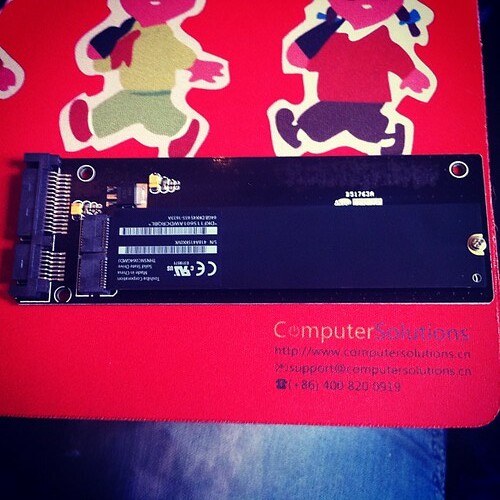
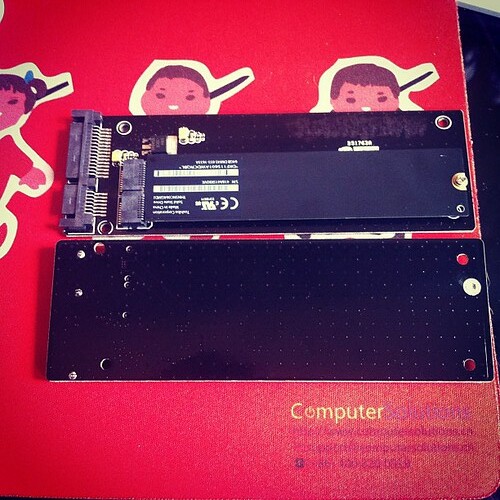
Front and back – not much circuitry really.
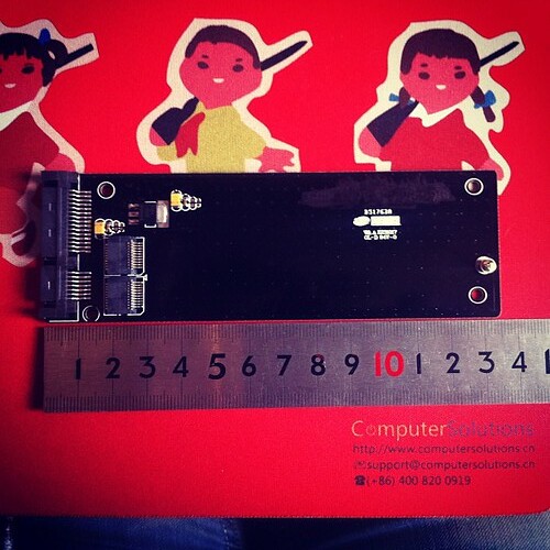
13.5cm length (which means can’t really be used in a laptop, sadly)
Side by side comparison with populated and unpopulated adaptor
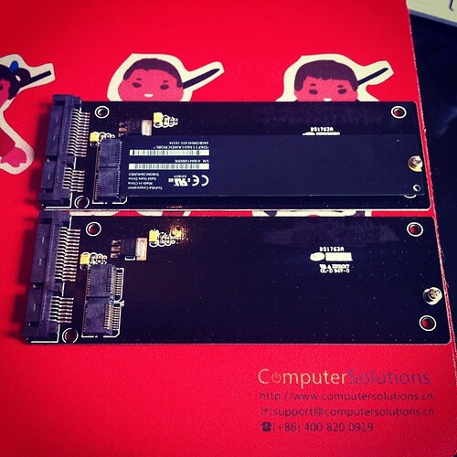
Unfortunately they’re not much use in anything but a desktop at the moment due to length (13.5cm), but it does bring new life to the ones I have 🙂
Bonus, its a crapload cheaper for Air SSD’s than “normal” SSD’s – roughly half the price, so I can update some of the random desktops on the office.
Win / win!
If anyone is interested in purchasing some, let me know, and I’ll organize some more.
If you get similar messages to this when you use apt-get
perl: warning: Setting locale failed.
perl: warning: Please check that your locale settings:
	LANGUAGE = (unset),
	LC_ALL = (unset),
	LC_CTYPE = "UTF-8",
	LANG = "en_US"
    are supported and installed on your system.
perl: warning: Falling back to the standard locale ("C").
locale: Cannot set LC_CTYPE to default locale: No such file or directory
locale: Cannot set LC_MESSAGES to default locale: No such file or directory
locale: Cannot set LC_ALL to default locale: No such file or directory
and the advice to
dpkg-reconfigure locales
doesn’t work, then try this –
export LANGUAGE=en_US.UTF-8
export LANG=en_US.UTF-8
export LC_ALL=en_US.UTF-8
locale-gen en_US.UTF-8
dpkg-reconfigure locales
Short and sweet solution.
8
Macbook Pro top replacement issue – or how I fixed my Macbook and sorted out the function keys.
I’ve been buying broken Macbook’s in SA when I’ve been home, for repair in China.
My latest purchase is a pre unibody Mac Book Pro that had been dropped – the top case was dented,and the screen shattered.
The LCD was fairly painless to replace – I’ve done quite a few already on various models, and I have a bazillion suppliers for raw panels.
The top case was a little more problematic – I ordered 2 consecutive replacements off of Taobao, but unfortunately the delivery company (ShenTong) destroyed both in shipping. Took about a month to sort that out and find a yet another replacement with explicit instructions please not to send via ShenTong (aka destroyer of parts).
The third case arrived in pristine condition, and I installed the keyboard from the previous case, only to find that the function keys didn’t work, and the caps lock didn’t work.
It wasn’t a hardware issue with the keyboard, as it worked fine in another laptop. I even ordered another one just to make sure.
A bit of googling revealed that the keyboard kext gets the layout from the USB hardware ID present in the top case.
As my top case didn’t quite match up hardware id wise, I was seeing that as an issue.
Fixing this is a bit tricky, but doable.
First up was to find out what the hardware id is for the USB case.
In my case this was as below (snarfed from System Information / USB)
Apple Internal Keyboard / Trackpad:

  Product ID:	0x0231
  Vendor ID:	0x05ac  (Apple Inc.)
  Version:	0,70
  Speed:	Up to 12 Mb/sec
  Manufacturer:	Apple, Inc.
  Location ID:	0x5d200000 / 3
  Current Available (mA):	500
  Current Required (mA):	40
Product ID is the useful bit – 0x0231 = 561 in decimal.
So, we need to lookup 561 in the kext (driver) for the keyboard.
In Lion / Snow Leopard, this is in the AppleUSBTopCase.kext over in System / Library / Extensions.
If you open up that kext, it has the plist for the keyboard layouts over here –
AppleUSBTopCase.kext » Contents » PlugIns » AppleUSBTCKeyEventDriver.kext » Contents » Info.plist
Open up the Info.plist, and look for the Product ID that matches your Product ID – in my case 560.
The key FnFunctionUsageMap contains the mapping for the keyboard. In my case I had to change it to this:
FnFunctionUsageMap
0x0007003a,0x00ff0005,0x0007003b,0x00ff0004,0x0007003c,0x000c00e2,0x0007003d,0x000c00ea,0x0007003e,0x000c00e9,0x0007003f,0x00070083,0x00070040,0x00ff0006,0x00070041,0x00ff0007,0x00070042,0x00ff0009,0x00070043,0x00ff0008
Each value is a pair – first the key number, then the value to set it to.
0x0007003a = F1
0x0007003b = F2
…
My above settings are for
F1 = brightness down
F2 = brightness up
F3 = mute
F4 = volume down
F5 = volume up
F6 = num lock
F7 = Expose
F8 = Keyboard Light off
F9 = Keyboard Light down
F10 = Keyboard Light Up
F11 = n/a
F12 = n/a
I got these values from here –
// usage IDs from the hid
#define FF_BRIGHTNESS_DOWN_ID_LAPTOP @”0x00ff0005″ // for laptops
#define FF_BRIGHTNESS_UP_ID_LAPTOP @”0x00ff0004″ // for laptops
#define FF_BRIGHTNESS_DOWN_ID_EXTERNAL @”0xff010021″ // for external keyboards
#define FF_BRIGHTNESS_UP_ID_EXTERNAL @”0xff010020″ // for external keyboards
#define FF_EXPOSE_ID @”0xff010010″
#define FF_DASHBOARD_ID @”0xff010002″
#define FF_ILLUMINATION_TOGGLE_ID @”0x00ff0007″
#define FF_ILLUMINATION_DOWN_ID @”0x00ff0009″
#define FF_ILLUMINATION_UP_ID @”0x00ff0008″
#define FF_VIDEO_MIRROR_ID @”0x00ff0006″
#define FF_REWIND_ID @”0x000C00B4″
#define FF_PLAYPAUSE_ID @”0x000C00CD”
#define FF_FASTFORWARD_ID @”0x000C00B3″
#define FF_MUTE_ID @”0x000C00E2″
#define FF_VOLUME_DOWN_ID @”0x000C00EA”
#define FF_VOLUME_UP_ID @”0x000C00E9″
Once I’d done that, I also needed to rebuild (or in my case build), the Kext cache so that the OS would use it on next reboot.
Heres how to do that in Lion
sudo kextcache -v 1 -a i386 -a x86_64 -m /System/Library/Caches/com.apple.kext.caches/Startup/Extensions.mkext /System/Library/Extensions
…oh, and lastly, reboot of course!
Post reboot my function keys were working normally.
The caps lock key is still non-functional, but I’m ok with that, as its means a bit more work for little effort.
I may look into setting up a special plist to override the usb_id its getting from the hardware via the method here –http://www.projectosx.com/forum/index.php?showtopic=798
..but again, time vs effort…
Still, my Macbook is working now more or less, so its good enough for me 🙂
Of course, subsequently to doing this the hard way, I found a program to do it all for me!
http://pqrs.org/macosx/keyremap4macbook/
Suggest unless you are a masochist, use that!
We use xcache as a php caching mechanism on our servers.
Its pretty painless for us for the most part.
One of our clients did complain that their app was now crapping out.
A check of the software forums for that app (ActiveCollab) showed that it was an issue with PHP5.3.2 and XCache and ActiveCollab.
So, needed to disable Xcache.
This should be relatively easy I thought, but the documentation sucks, so took a while to find out how.
Its pretty simple to do though.
Assuming you’ve allowed htaccess files in apache, you can do the below –
Add an htaccess file in the root folder of the website with the following info
php_flag xcache.cacher Off
php_flag xcache.size 0
php_flag xcache.stat Off
Thats it.
17
Windows Drivers tips and tricks or How I learned to stop worrying and love the bom^H Microsoft.
Despite my pendance for semi obscure cultural references (its most of the title from a decent Peter Sellers satire), I do often find useful things that people can use.
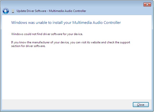
One of the things that is annoying about Windows especially is its resolute failure to find drivers when you run the “search the internet” option in XP, Vista^Hno such OS, and Win7
Example of this below:

At first we’re hopeful – maybe the gods will deign to assist us in our hour of need.

…but then reality comes crashing down, and we realise that we have to do the wild goosechase of running around trying to find drivers.
Wouldn’t it be nice if Microsoft actually got their act together, and put drivers online like they probably intended to?
Well, our prayers have been answered, but in typical Microsoft fashion, we still need to jump through multiple hoops to do so.
So… lets say we have some hardware in our computer that has the mystery yellow ? icon of unhappyness in Device Manager.
What to do?
First off, lets go visit Microsofts rather good, but also rather unpublicized site here:
http://catalog.update.microsoft.com
Install the cab file and sign away your life, rights and grandmother, as per standard clauses.
Bookmark this page, as its going to become very useful.
Done?
Ok, good. Now lets return to device manager.
As I’m writing this from a Win7 box, I’ll pick something that doesn’t appear to have Windows 7 drivers post install.
SIS900 Ethernet.
If you visit the SIS website, they don’t have drivers for Windows 7.
Not all is lost though.
Lets search that site we just bookmarked

Yes!
Windows 7 drivers for the SIS900. I’ll talk about the rather convoluted way we have to use these in a second.
For now, lets go with another example.
Lets say we have an unknown device in Device Manager in Windows, and we don’t really know what it is.
All devices have something called a hardware ID. This is what identifies the hardware so Windows can lookup what driver is appropriate.
I’ll pick another driver from this desktop I’m busy installing drivers for at the moment.

As you can see, we can see a list of hardware ID’s in the details tab of the property window for that device (Open up device manager, right click the ?’d device, and click properties to bring this window up)
In Windows 7 we can finally copy the text, yay!, in older Windows OS’s we need to write down those numbers.
Lets swing back to the Microsoft site, and search for that Device_ID&Ven_ID
PCI\VEN_1039&DEV_7012&SUBSYS_0C4C105B

Woohoo! Nice and easy – right?
Um no, remember, this is Microsoft, no Apple, so ts a little bit more complicated to use them.
Click on the driver thats appropriate for the OS in use, add to basket, then download. You may need to try a couple of different versions if the first one you try doesn’t solve the driver issue, so pick two or three different ones.
I suggest save to the desktop.
In a few minutes you’ll find that you have a folder on the desktop with the driver in a cab file.
A cab file? Hmm, thats not very useful, right?
Exactly…
So, we need to unpack that cab (cabinet file), and take out the juicy driver goodness so we can finally get our hardware working.
My favourite tool for this would be Winrar, so download WinRar, and install (http://www.rarlabs.com).
Installed?
Good, now right click on the cab file, and choose extract files…

Next, choose an appropriate folder name, as the defaults are too long, and winrar can’t extract the files.

In this case, as its an Audio driver, I used the cunning name of “Audio” for the folder.
Lets have a look at the folder, and see if it has an installer (usually something along the lines of Install.exe or Setup.exe. In this case it doesn’t, so off we go back to control panel, device manager.
We’ll try install using the driver we just downloaded.
Right click on the device, click Properties, Update Driver (usually something similar in most Windows OS’s)
Tell windows we have our own driver, and point it at the folder we just extracted.
If you are lucky you should see something like this:

Woohoo, win!
Whats strange is that Microsoft seemingly goes out of their way to make this more complicated than it really should be.
They’ve had a driver update from the internet option in Windows since XP days. They have this nice site with all the drivers. They make it rather convoluted to use though.
Wouldn’t it be nice if they put it all together and automated it?
Oh well, until we reach that perfect world, the instructions above should help you with any driver issues for Windows.
No more downloading from dodgy driver support sites, or trawling the internet for providers driver files. Get them from Microsoft instead!
31
Kudelski N3 bits and pieces.
Kudelski N3 bits and pieces, plus thoughts on key / rsa extraction from flash.
N3 Notes mostly from forum posts by TheCoder
These are notes for future reference more than anything else, so please no excited emails about how its wrong, or right, or can I hack your box.
—
There are three different pairing methods used N3 boxes presently. These are DT06, DT08 and Secondary key.
The DT06 method transfers a compressed form of an rsa pq keyset from which the CAM public/private rsa keyset and its associated modulus can be derived.
The DT08 method transfers the cam modulus along with the IRD number of the married box. The public rsa key is not transferred but it is implied that the box already knows this value.
The Secondary key method does not involve a transfer. It imples that the box already knows the cards matching CAM modulus and rsa public key value.
Various boxes, depending on make/model, may use any of the above pre-pair key transfer methods but it could be useful to know which box uses which method.
http://www.digital-kaos.co.uk/forums/f10/people-n3-cards-82421/
Instructions:
1 Stick your N2/N3 card in your card reader
2 Run NagraEdit – DO NOT ATTEMPT TO READ YOUR CARD !!!
3 Select the Comm Tab. This should give you an upper and lower text pane
4 Cut/Paste the scriptt below into the top pane
5 Press the “Send D2C” button/icon
6 Results should appear in bottom pane
7 Interpret your results based on info below.
Script – Read DT06/DT08
Code:
rs
tx 21 C1 01 FE 1F
rx
tx 21 00 08 A0 CA 00 00 02 12 00 06 55
dl 02 00
rx
dl 02 00
tx 21 00 09 A0 CA 00 00 03 22 01 00 1C 7E
dl 02 00
rx
dl 02 00
mg *
mg *** DT06 info ***
tx 21 00 09 A0 CA 00 00 03 22 01 06 13 **
dl 02 00
rx
mg DT06 response1
dl 02 00
tx 21 40 09 A0 CA 00 00 03 22 01 86 13 **
dl 02 00
rx
dl 02 00
mg DT06 response2
mg *** End DT06 info ***
mg *
mg *** DT08 info ***
tx 21 40 09 A0 CA 00 00 03 22 01 08 13 **
dl 02 00
rx
mg DT08 response1
dl 02 00
tx 21 00 09 A0 CA 00 00 03 22 01 C8 55 **
dl 02 00
rx
dl 02 00
mg DT08 response2
tx 21 40 09 A0 CA 00 00 03 22 01 88 55 **
dl 02 00
rx
mg DT08 response3
dl 02 00
mg *** End DT08 info ***
*******
Just to clarify :
The important bits your looking at are the DT06/DT08 responses (the bits that start with Rx: )
ie RX: 12 00 15 A2 11 08 E0 00 00 00 5E 01 20 00 00 00
00 00 00 00 00 00 90 00 B3
RX: 12 40 15 A2 11 00 00 00 00 00 00 00 00 00 00 00
00 00 00 00 00 00 90 00 64
RX: 12 00 15 A2 11 00 00 00 00 00 00 00 00 00 00 00
00 00 00 00 00 00 90 00 24
and
RX: 12 40 57 A2 53 00 00 00 00 00 00 00 00 00 00 00
00 00 00 00 00 00 00 00 00 00 00 00 00 00 00 00
00 00 00 00 00 00 00 00 00 00 00 00 00 00 00 00
00 00 00 00 00 00 00 00 00 00 00 00 00 00 00 00
00 00 00 00 00 00 00 00 00 00 00 00 00 00 00 00
00 00 00 00 00 00 00 00 90 00 64
If the responses vary significantly from the above, with the 00’s replaced with some varying data, then its likely your card had the specified tier and is probably using the corresponding pairing method.
If the DT06 response contains lots of 00’s then its NOT DT06 pairing
If the DT08 response contains lots of 00’s then its NOT DT08 pairing
If its not DT06 or DT08 then its probably secondary key.
For non DT08 cards (mostly the newer boxes) each box has a unique cam_n already built into its firmware – this can only be extracted from the actual box itself.
About the Algorithm,
N2 encrytion was based on the following algorithm ->
decrypted message = ( (IDEA( ( (EncryptedMsg ^ 3)Mod N1) ,IdeaKey) ) ^3) Mod N1
Thats 2 distinct algorithms. An RSA algorithm (performed twice) and an IDEA algorithm.
The key for the RSA algorithm is something like –
RSA EMM-G=15A811B2065DF39CD48C9C958E7B406345295B09D0E9A18A 9B92C5FD7761CAAFAB830880F1F06B4E4477F157EA10D0AFC3 FDDB1ED2E7E83E89F03FF81237047DB76F79D6A2CFD75A7255 D72E52E7F47B96C2DFBDEBFC80CE927F6AD351FDF0BF8DA13F F62295BFBAF29035A230136D0B4AA99D38DD8B0465F2C709FC 8818173C
Which, as you can see, is a 128 byte (1024 bit) number. This is the main encryption key for EMM decryption.
The IDEA algorithm, which acts as an inner layer to the RSA has a standard 16 byte (128 bit) IDEA key.
There is no algorithm in N2 (or N3) that only uses an 8 byte (64 bit) key although some providers have opted to use 3DES rather than IDEA as an inner layer. This uses three separate 8 bye (64 bit – only 56 bits used) keys to form an amalgam 168 bit DES algorithm.
If Using DT08 (0a) on the card :
The Dt08 (0a datatype on card) is created by the provider and sent to the card at sub time.
The dt08 contains the Cam N public rsa key along with ird/boxkey.
The dt08 is IDEA encrypted with the Idea Key made from ird/boxkey/inverted ird.
The dt08 is RSA encrypted using Ird N (public rsa key) and Ird D (private key and uknown by anyone but provider).
Ird N = N1 xored N2
Ird N1= A4E9B585932F90282FD70C908176E8605E6B2CE629335A0FC1 5B31DAB0BFC6FEEB88CFC69649994CD3FE039C9965C620C4D5 828E9153998EE4AE0E8C25644DF3 xor
Ird N1= 237280AAB36BE4B21FC71FBF08218E532A545E744D7B007FF8 69BA426831C4AC653F3825ADE9358FCD1F0239EC447CBC2765 CC0AEBE437AF2270FC461C2FA042
Ird N = 879B352F2044749A3010132F89576633743F729264485A7039 328B98D88E02528EB7F7E33BA0ACC31EE101A57521BA9CE3B0 4E847AB7AE21C6DEF2CA394BEDB1
The Ird N1,N2,Ideakey exist in the tsop.
Ird E = 3
Ird D = UKNOWN, this is the reason you can’t create your own dt08 without changing the N1/N2 on the tsop, you must know Ird D.
DT08 (0A) = IdeaEncrypt(CamN/Ird#/Boxkey/Idea Signature,Ird_Ideakey) ^ D mod Ird N.
Ird requests DT08.
Card sends back the dt08 (0a)
Ird decrypts the dt08.
Decrypted dt08 = IdeaDecrypt(DT08,Ird_IdeaKey) ^ 3 mod Ird N.
It checks the ird # and boxkeys in the Decrypted 08 if they match what is on ird,
it stores the Cam N in the decrypted 08 in ird memmory.
If Using Secondary Key (SK) on the Ird.
Ird checks for SK exists on the ird, if it does, the dt08 will never be requested/ignored from the card.
Ird validates the SK with idea signature in the SK (using IIIIIIII01924314051647990A9C4E1 where I = irdnumber).
Ird takes the Cam N in the SK and puts it in ird memmory
Note : Cam N is not even encrypted in the sk, very weak method compared to dt08.
Later, establish session key (0C datatype on the card):
Ird requests 2a data from card.
Random 2a is sent from card to ird.
Ird performs some Idea signing (leave it to you to look up 2a/2b routines)
Ird comes up with session key from the 2a message sent from Cam.
Ird encrypts the session key with rsa.
Encrypted 2B = (2B data with 16 byte session idea key) ^ 3 mod Cam N.
Sends encrypted data back to card in 2b message.
Cam decrypts 2B with Cam N, Cam D. Decrypted 2B = (Encrypted 2B) ^ Cam D mod Cam N.
If valid, store session key in ram and on card for later use.
This all happens as ird boots.
When you select a channel.
Ird sends Cmd 07 ECM message with control words encrypted.
Cam decrypts the control words rencrypts them with Idea encryption using the session key established above.
The ird then requests the control words.
The Cam sends them back in the 1C response.
The ird decrypts the control words with with Idea encryption using the session key established above.
Sends the control words to the mpeg decoder.
8 seconds of video.
Repeat 07/1C process over and over.
——–
and pay special attention on CMD$2A ??
it should reply the CAMID serial number + 64 bytes random key generated and then shortly after encrypted with the CAM(AKA Conditional Access Module or SmartCard) RSA primary 96 bytes from the card… the so famous RSA modulus keys 96bytes at eeprom $8xxx on the ROM110 days.. From the card (this cmd is also the first step of the SessionKey negotiation)
shortly after the receiver receives this card reply.. and will decrypt it using the Secondary Key which is also 96bytes, this key is build up by using the following information stored in the receivers flash..
IR IR IR IR ZZ ZZ ZZ ZZ ZZ ZZ ZZ ZZ 00 03 F1 F1
F1 F1 F1 F1 F1 F1 SK SK SK SK SK SK SK SK SK SK
SK SK SK SK SK SK SK SK SK SK SK SK SK SK SK SK
SK SK SK SK SK SK SK SK SK SK SK SK SK SK SK SK
SK SK SK SK SK SK SK SK SK SK SK SK SK SK SK SK
SK SK SK SK SK SK F2 F2 F2 F2 F2 F2 F2 F2 CR CR
total 96 bytes..
IR = Receiver serial number
XX = Unimportant
EE = RSA public exponent for STB
F1 = SK signature 1 used to calculate the box key
F2 = SK signature 2 used to calculate the box key
SK = RSA public modulus N
CR = CRC Checksum
BB = BoxKey result from xoring F1 with F2 keys stored in the flash firmware from the receiver
once we decrypt the cmd2A we extract from inside the original 64byte random key generated in the card, then we will apply the IDEA encryption algo on the first 32bytes from the 64 byte random key to hash out the session key.
So this first 32 bytes are extracted from the 64byte random key and will be encryted using the IDEA SIGNATURE key… this key will be generated by the following information
IdeaKey generation
BB BB BB BB BB BB BB BB + CC CC CC CC + CA MI DC AM
BBBBBBBBBBBBBBBB = Boxkey result from F1 xor F2
CCCCCCCC = IRD number from receiver stored in Flash firmware
CA MI DC AM = CAM ID or Smart Card serial number converted in HEX, which can also be extracted by simply sending INS CMD$12 to the card..
so the IDEA signature key for encrypting the first 32bytes extracted from the 64 random seek key is
BBBBBBBBBBBBBBBBCCCCCAMIDCAM
once applied the IDEA encryption we will have the result 16 byte sessionkey.. which will be stored in the receiver flash for a few hours… to be more precise around 5 hours..
Now going back to the calculation done before, the receiver decrypted the cmd$2Aencrypted by the card with the RSA primary 96 stored in the card.
once decrypted it simply just extracted the first 32bytes of the 64 byte seed key generated by the card. this 32 bytes were used for calculation of the 16byte sessionkey..
but, before the 32byte keys was taken for the idea signature encryption.. the receiver.. re-encrypted the 64byte random key using the SECONDARY KEY RSA 96 stored in the receiver flash, which i just stated above how to get this key…
and will send it back to the card on cmd$2B
the card will receive the cmd$2b and will decrypt it using the PRIMARY RSA modulus key 96.
and will extract just the first 32bytes.. and by using the BOXKEY+IRD+CAMID stored in the card, the card will also calculate the same 16 byte session key.
in orde to make the card pairing , u need to know the RSA_N+BOXKEY+IRD NUMBER+CARD SERIAL number or CAMID…
then with them all together we can start comunication between the card.. and on the CMD$2A and $2B we will have the SessionKey negotiation which i just explained previously.
if for example on one side or the other we have different BKand RSA… we will a session key failure.. and without this Sessionkey we will not be able to decrypt the CM$1C or $9C related stuff
this means that if negotiation of session key succeds, then the receiver will send the ECM$07 to the card, which will then be decrypted by simply just using the ECM RSA modulus key and the ECM IdeaKey to decrypt the Control Words / CWs.
once they are decrypted the card will send them to the RECEIVER.. this is normally done via CMD$1C obviously this CMD is encrypted with the Sessionkey 16 BYTES described above.. once it arrives at the Receiver end, you will use the same Sessionkey 16byte to decrypt that CMD$1C and extract the REAL DCWs Decrypted Control Words to open up the Video and Audio stream related for that XX amount of seconds…
Now this Session key is refreshed every 5 hours.. this means that every 5 hours a new session key is produced.. so every 5 hours the card generates another 64byte random seed key using other RSA algo inside the card.., and will then send this 64 byte seed key to the receiver again.
Shortly followed by all the procedure described above to extract the new session key again.
—————-
Given that ==================================================
SK 96 BYTES
==================================================
11111111<----------------------------FIRST 4 BYTES---- IRD
XXXXXXXXXXXXXXXXXXXX<--NEXT 10 BYTES---- unknown
1111111111111111<--------8 BYTES---- Y1---WRITE DOWN
==================================================
11111111111111111111111111111111-_
11111111111111111111111111111111-_-_"N" 64 Bytes
11111111111111111111111111111111-_-
11111111111111111111111111111111-
==================================================
1111111111111111<-------8 BYTES--- Y2-----WRITE DOWN
XXXX<-------------------2 BYTES--- CHECKSUM
==================================================
Y2 Xor Y1 = BOXKEY
==================================================
006e convert from hex gives you 110 bytes block cipher
ird 4 bytes
bk 8 bytes
sk 96 bytes
leaving us with 02bytes used to encrypt, decrypt above.
eg:
00 00 00 6e 34 0d 20 1c 03 03 70 80 5a 8e dd 24
ac cc a4 a6 e2 da 86 91 29 18 0b a6 23 6d fa c4
05 7f 1b 20 97 eb 0c 19 b3 39 2f 1e cb 9b 67 4d
ed 10 f5 65 ec 0d c7 35 ac f0 b8 89 b0 51 59 22
69 85 d5 f1 93 48 7a 84 6e 1f b4 24 83 79 db 02
4d b0 9c 5e 8b df 89 57 9c 5a 7f 9a cc 87 51 3b
15 6b 15 cc c4 2f 66 e7 e6 75 4f 24 f2 07 85 0d
db b0 3d e2 64 dd e9 54 ad 77 60 e7 8f a6 cd a6
46 c3 b8 fa e4 e7 51 2d 6a 2f 95 68 56 b5 78 34
17 6b b8 48 38 87 c4 95 e5 b0 41 2c 95 e1 24 aa
4b 2a 6f 8c 90 53 29 a9 6b 3d 0a b5 92 1c 95 ec
72 b9 54 a9 99 f5 f3 dd f4 0f 60 c3 25 5b 5b 81
22 e8 79 c5 be 8f 3c 89 2b 8a ad ba 27 b0 c2 f7
b1 4f 08 d5 37 2a 97 c5 f0 07 9d 99 be c7 8a a9
cf 5a c5 45 ce 1e 25 43 81 95 7a 22 33 ed 93 74
Gives:
00 00 00 63 (length)
0d 20 1c 03 03 70 80 5a 8e dd (unknown)
24 ac cc a4 a6 e2 da 86 (y1)
91 29 18 0b a6 23 6d fa c4
05 7f 1b 20 97 eb 0c 19 b3 39 2f 1e cb 9b 67 4d
ed 10 f5 65 ec 0d c7 35 ac f0 b8 89 b0 51 59 22
69 85 d5 f1 93 48 7a 84 6e 1f b4 24 83 79 db 02
4d b0 9c 5e 8b df 89 (64 bytes)
57 9c 5a 7f 9a cc 87 51 (y2)
Y2 XOR Y1 = 0x579c5a7f9acc8751 xor 0x24accca4a6e2da86 = 42 12 8C F2 39 39 55 FA
So, a flash dump would be helpful..
Possible Scenario's -
BGA, TSOP, TLGA etc.. desoldering for Flash.
Put in a socket. eg from
http://shop37051047.taobao.com/ or http://shop34694309.taobao.com/?search=y
Pop flash back onto something else, read, dump. eg
http://item.taobao.com/item.htm?id=7422440993
Get box key, rsa key (if req. based on a check of DT type from the actual subbed card)
Pop flash back in socket.
Been there, done that for data recovery on faulty flash drives, plus most of the places I know down at QJlu have SMD / BGA desoldering capability or better.
Bunnies blog is fairly good at explaining the basics (albeit for xbox) – http://www.xenatera.com/bunnie/proj/anatak/xboxmod.html
Most boxes use ARM based SoC’s for things. Also possible to just throw up a dev board, and interface to that.
Although most boxes also have some form of OS running, so just as feasible to dump flash that way also assuming serial or jtag access and a bootloader is available.
Amusing that people like http://www.flashbackdata.com/blog/?p=195 claim this is hard – there are plenty of tools for this already out there eg softcenter, pc3000, plus all the local chinese stuff. Semi ok forum here talking about flash recovery, although not as technical as I’d like.
http://forum.hddguru.com/hard-disk-drives-english-forum-f12.html
Once key(s) are had, then I can use my own decoder rather than the crappy one the broadcaster uses.
Yay.
Had a client come into the office today with a locked iPhone.
Normally this isn’t really a big deal (assuming that there is a hack for it), but in this case, it was a little more complex, as he didn’t have working wifi.
PwnageTool has a great feature where you can add Cydia Packages to a custom firmware, so that you can prepackage the firmware already to go.
So, I opened up PwnageTool, added the http://repo666.ultrasn0w.com/ site to the Cydia sources section in advanced, and tried to load in Ultrasn0w.
Life isn’t easy, and it didn’t work.
But why didn’t it work?
I took a look at a working site, and checked out the differences between their package section and Ultrasn0w’s.
Ultrasn0w is hosted on repo666.ultrasn0w.com
While their website doesn’t really tell you much useful information, a bit of googling lead to some info.
The .deb file (debian package file) on their site is at http://repo666.ultrasn0w.com/ultrasn0w.deb
Cydia usually needs stuff in a particular format, so I next checked out how one makes a repository.
This is documented at Saurik’s site here – http://www.saurik.com/id/7
Basically, you throw files into a folder and make a Packages file.
The example given on Saurik’s site is this:
/web/apt/xmpl]# dpkg-scanpackages -m . /dev/null >Packages

 ** Packages in archive but missing from override file: **

  com.saurik.myprogram
Wrote 1 entries to output Packages file.
[root@desktop:/web/apt/xmpl]# bzip2 Packages
[root@desktop:/web/apt/xmpl]# ls -la *
-rw-r--r-- 1 root root 906 2008-07-01 07:48 MyProgram.deb
-rw-r--r-- 1 root root 380 2008-07-01 08:00 Packages.bz2
[root@desktop:/web/apt/xmpl]#
So, it appears we need a Packages.bz2 file.
Being adventurous, I decided to setup my own repo, and stuck the .deb file for Ultrasn0w in there.
Followed the instructions and created the Packages.bz2 file.
Tried again in PwnageTool, and… No go.
Hmm.
Does http://repo666.ultrasn0w.com have a Packages.bz2 file?
Why yes it does.
Take another look at the working one – ahah says my brain.
They point the folder to the _uncompressed_ Packages file.
I guess PwnageTool doesn’t support compressed Package list files.
So, I try that out using an uncompressed file.
Created the Packages file with
dpkg-scanpackages -m . /dev/null >Packages
and try again.
Better – I’m getting a result now with my repo when I click refresh.
However, I can’t seem to be able to download any files…
So, lets take a look at whats happening in my apache logs.
58.37.213.199 - - [07/Mar/2011:20:50:52 +0800] "GET /dists/Packages HTTP/1.1" 200 1643 "-" "PwnageTool/4.2 CFNetwork/454.11.5 Darwin/10.6.0 (i386) (iMac9%2C1)"

58.37.213.199 - - [07/Mar/2011:20:51:06 +0800] "GET /./mobilesubstrate_0.9.3228-1_iphoneos-arm.deb HTTP/1.1" 404 1184 "-" "PwnageTool/4.2 CFNetwork/454.11.5 Darwin/10.6.0 (i386) (iMac9%2C1)"

58.37.213.199 - - [07/Mar/2011:20:51:42 +0800] "GET /./ultrasn0w.deb HTTP/1.1" 404 1164 "-" "PwnageTool/4.2 CFNetwork/454.11.5 Darwin/10.6.0 (i386) (iMac9%2C1)"
Aha! While its successfully found the repo now, its looking for the files in the wrong folder – my repo is in /dists, and its looking in the root folder.
Seems the Saurik instructions are a bit mangled, or the Package generator is a bit silly.
Quick look at the helpfile shows it needs the folder via -m
So I went up a level, and regenerated my file.
cd ..

dpkg-scanpackages -m dists > dists/Packages
Yes, it works!

Now PwnageTool can download my file finally. Yay!
I just need to select it in PwnageTool / Packages as below, and build my ipsw to test.

Now I can finally make my own Ultrasn0w firmware woohoo!
Not as hard as it seems, but not as easy either!
I’ll leave my UltraSn0w repo at http://www.sheed.com/dists/ for now, but will probably move it elsewhere at some point, and update this post. So, if you need it, get it while you can.
Lawrence.
This was posted by myself over at BimmerForum’s, but as China’s Firewall is being particularly unpleasant these days about what sites I can and cannot visit, I thought I’d repost it here, so its more accessible for me.
Note – I no longer own a 7 series, so any requests for modded rom’s should probably be accompanied with nice gifts to persuade me to do the work involved 🙂
As I saw people asking about Tuned ROM’s in another post I thought I’d do some research.
Its quite niche – hence the ridiculous pricing people charge for roms – time is money though!
Here’s my research so far. I’m basing it on the E32 735iL 1989/1990, as thats what I own (and can test for).
Googling for E32 735iL gives:
ELECTRONIC CONTROL UNIT, DME MOTRONIC
BOSCH 0261200179
BMW 1730697
*26SA0840*
Vehicle Applicability:
1986-1993
BMW 3′ E30 320i Touring 2.0 95kW/129PS (M20/ 206EE/KA)
BMW 5′ E34 535i 3.4 155kW/211PS (M30/346KB)
BMW 6′ E24 635CSi 3.4 155kW/211PS (M30 B35)
BMW 7′ E32 735i 3.4 155kW/211PS (M30/ 346KB/EC)
BMW 7′ E32 735iL 3.4 155kW/211PS (M30/ 346KB/EC)
ELECTRONIC CONTROL UNIT, DME MOTRONIC
BOSCH 0261200179
BMW 1722611
*26RT2794*
Vehicle Applicability:
1986-1993
BMW 3′ E30 320i Touring 2.0 95kW/129PS (M20/ 206EE/KA)
BMW 5′ E34 535i 3.4 155kW/211PS (M30/346KB)
BMW 6′ E24 635CSi 3.4 155kW/211PS (M30 B35)
BMW 7′ E32 735i 3.4 155kW/211PS (M30/ 346KB/EC)
BMW 7′ E32 735iL 3.4 155kW/211PS (M30/ 346KB/EC)
ETK however says
No.Description Supplement Qty Part Number Price
01AT-Control unit Motronic HARDWARE 1.3 1 12141738168 ENDED
01AT-Control unit Motronic HARDWARE 1.3 1 12141748258 $813.86
Whatever the actual revision used, its pretty clear we have a v1.3 Motronic.
Wiki (
) says:
|
The Motronic 1.1 System was used by BMW from 1987. This was then superseded in 1988 by the Motronic 1.3 system[6] that was also used by PSA on some XU9J-series engines (which previously used Motronic 4.1).[5]
The Motronic 1.1 and 1.3 systems are largely similar, the main improvement being the increased diagnostic capabilities of Motronic 1.3. The 1.3 ECU can store many more detailed fault codes than 1.1, and has a permanent 12-volt feed from the vehicle’s battery which allows it to log intermittent faults in memory across several trips. Motronic 1.1 can only advise of a few currently-occurring faults.[6] The systems include a knock sensor for ignition timing adjustment and the option for a lambda sensor, enabling their use with catalytic converter-equipped vehicles.[5] The ECUs have 2 injection outputs, and the injectors are arranged in 2 "banks" which fire once every two engine revolutions. In an example 4-cylinder engine, one output controls the injectors for cylinders 1 and 3, and the other controls 2 and 4. The system uses a "cylinder ID" sensor mounted to the cam-shaft to detect which cylinders are approaching the top of their stroke, therefore which injector bank should be fired. During start-up (below 600 RPM), or if there is no signal from the cylinder ID sensor, all injectors are fired simultaneously once per engine revolution.[6] |
DME / ECU 1.3 Info.
Tuning is set in 2D map.
Motronic 1.3 from 1989: The fault code memory is extended to contain all fault codes that are detected by the EMS.
In vehicles sold in the USA, when the ECU detects that a some faults are present it earths pin 15 and the Check Engine warning lamp on the dash will light. The lamp will stay lit until the fault is no longer present. A warning lamp is not fitted to vehicles sold in other markets. The faults that will turn on the lamp are mainly those concerned with emissions. Other faults are logged by the ECU but the lamp will remain out.
ECU (DME) sensors run off 5v
Download extended info here – http://www.opel-scanner.com/files/DME_1.1_1.3.pdf
DME bootup: (roughly paraphrased)
Interestingly enough I got to learn this properly via the tips and tricks for checking why the car doesn’t start..
Ignition switched on:
ECU earths 85 , 36 which causes relay to close and 30 is connected to 87 starting the fuel pump. (30+87 can be bridged manually under the green relay to test pump). Its opened for +- 1 second.
Next up it reads values from the CAS (Pulse Sensor). If it reads a speed signal (aka is it turning), so fuel pump stays on.
CAS is used to time the pulses (read from each turn of the flywheel), this is checked against the map file for correct speeds (need to use a multiplier for the map values vs the flywheel pins).
The Motronic ECU contains a fuel map with an injector opening time for basic conditions of speed and load. Information is then gathered from engine sensors such as the AFS, CAS, CTS, and TS. As a result of this information, the ECU will look-up the correct injector pulse duration right across the engine rpm, load and temperature range.
The injectors are arranged in two banks with injectors 1 and 3 (4 cylinder) or 1, 3 and 5 (6 cylinder comprising one bank, and injectors 2 and 4 (4 cylinder) or 2, 4 and 6 (6 cylinder) making up the other bank. Each bank is connected to the ECU via an independent ECU pin.
The Motronic 1.1 & 1.3 multi-point injection system pulses the injectors semi-sequentially and once every two engine revolutions. During engine start-up below 600 rpm the ECU pulses all injectors simultaneously. Once 600 rpm has been attained and if the ECU has received a signal from the CID sensor, each injector bank will be pulsed alternatively according to which pair of cylinders are approaching TDC. If a signal is not received from the CID sensor the injectors will remain on simultaneous operation. However, if the CID sensor subsequently sends a signal to the ECU after the engine has commenced running, the ECU will pulse the injectors semi-sequentially after the next deceleration phase – even if the CID sensor then ceases to send a signal.
—
Motronic troubleshooting (aka code readout)
The fault codes for these systems will appear on the check engine light when you turn the ignition key to the On position (but dont start it), then: fully depress the accelerator pedal, then fully release it. Repeat the depress,release cycle 5 times fairly quickly, but not too fast. It should be completed in a few seconds. What you are doing here is clicking the wide open throttle switch then the idle switch each 5 times. This signals the Motronic unit to send the fault codes by flashing the Check Engine light. You should see the light flash once then it will start flashing the 4 digit codes. If there are no faults, you should see the 1444 code (and 2444 if you have a 12 cylinder). The codes appear as a series of flashes for each digit. The flashes indicating one digit are about 1 second apart, the next digit appears after a couple second interval.
Get the codes from: http://www.unofficialbmw.com/repair_faqs/motronic.html
Other notes:
CPU most likely 8051
EEPROM 26C256, so 32KB / (32768 byte) chip. 28 pin.
Can also use a 64KB chip, just ground the relevant pins for which 32kb to use or burn one rom at appropriate location. Useful for running 2 tunes – eg original and second.
Tools available for this eg http://www.moates.net/font-size-12ti….html?cPath=31
Should run from a AT29C256 or similar.
ECU interesting pinouts:
Pin 55 TX
Pin 13 RX
Pin 2/19/24/26/14 GND
File layout (unchecked)
AFR idle: 0x662E (pos 26158)
AFR partial: 0x6662
AFR full: 0x6640
ign idle: 679A
ign partial: 0x67FE
ign full: 0x67CC
Sample bin file here: ftp://anonymous@bmw-wiki.org/ROMs/Mo…y-Motronic.bin
(I’m having issues downloading that from China, so haven’t checked it yet against the alleged layout).
Table calculations:
fuel maps correspond to (value/128 +1)*lambda_1
Bosch-Motronic f(n) = (n-30) x 0.75
some Bosch f(n) = (n-509) x 0.75
Bosch KE-Motronic und Mono-Motronic
f(n) = [(255-n)/6] +1
Motronic info
Very useful info for looking this up from http://motronic.ws/map201.htm
Maps 20 bytes each
Other thoughts – now we know what pinouts / values are expected in the system, guess just need to see what equipment provides appropriate inputs. eg, replace expensive spares with cheaper/better modern versions.
Most of the differences are usually in the mounting afaik, not the tech.
Motronic pinouts and board details here – http://www.e34.de/tips_tricks/motronic/m1_3.pdf
Lots of people working on this kind of thing with software like tunerpro / xdf (map) files.
*Good* forum for info (although not relevant to the Bosch ECU’s, but concepts / strategies same)
http://www.thirdgen.org/techboard/di…uide-book.html
The motronic 1.3 software in most of the E32’s should be fairly easy to modify – its all been documented well online before, so just a matter of getting a few rom files for specific models, and comparing tables.
Shogun has at least one rom (as he’s burning and selling them according to another post).
I can extract the current one from my DME and make a bin file for comparison.
We also have the rom from ftp://anonymous@bmw-wiki.org/ROMs/Mo…y-Motronic.bin
Should be enough to see where the changes are for the E32 / 8051CPU Motronic 1.3 anyway, so that I can tweak.
Another lucky thing is that I also used to write embedded software on 8051 cpu years ago (although I’ve forgotten it all by now)
Any interest in this from others (I’ll need more rom’s though)?
As my car currently has only 1 key, I thought I’d do a little bit of research into getting another one.
BMW quoted 2000rmb, which although understandable, is a little bit expensive. That doesn’t include the remote functionality in the current key either.
A check of taobao shows that you can buy blanks for slightly less – in the 30rmb range.
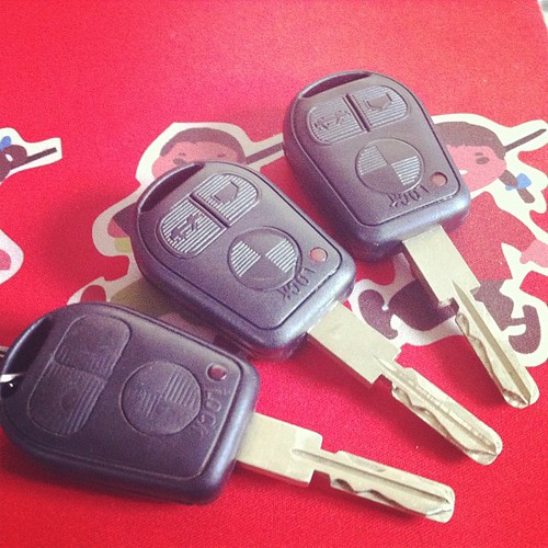
Mine is a 3 button remote, rather than a 2 button remote.
Images of both below:


Yes, I realise that these are just keys, and don’t contain the remote stuff either, but as a spare, its all I really need.
There is a fly in this ointment though. All European cars post 94 are mandated to include anti-theft immobilizers, which in BMW’s case involves checking for a transponder, so a key won’t start the car.
BMW calls this system EWS – Electronic Watchdog System.
A datasheet aimed at BMW workshop staff on EWS is here BMW EWS Overview and Worksheet
The infrastructure looks something like this:

I could buy a small board to bypass the EWS (about 130rmb), but I like the idea of having the anti-theft still working.
So, how does the EWS2 do the immobilization in my car?
A little bit of research shows that my current BMW (a 96 E36 import from German) uses BMW’s EWS2 for antitheft. This appears to be based on a motorola chipset ( XC424114CFN ) for the immobilizer side, and its relatively easy to read out or reflash the existing data from the chip if necessary should I need to do so.
eg if I lost all my keys, and needed to start from scratch. There are 3rd party tools galore that go into that eg CarProg, so not much point looking at that for me.
Lets look at the transponder side.
The transponder in my current key is a Philips PCF7930
This comes in a series – PCF7930, PCF7931, and PCF7935, and PCF7936
The main differences between the transponders are as follows:
PCF7930 – can read / write data.
PCF7931 – write once (one time programmable), read data.
PCF7935 – it has 2 area’s of memory general, and shadow memory, and both are read / write.
PCF7936 – it adds a crypto mode to the 7935 functionality.
The PCF7936 is also referred to as a Hitag2.
This is also the transponder current generation of BMW’s are using eg the E90/E92/E94’s
They’re quite simple devices really, a datasheet for them is here – PCF7930 / 31 / 35 Datasheet
They essentially have a few bytes of memory to work with.
32 bytes for control, and 80 bytes for user data.
Physically they’re about half the size of a fingernail and a few mm thick.
They look something like this –

A quick search on taobao shows that a PCF793x sells for between 17-20rmb or so.
So, so far I can get the key for about 30 odd, and the transponder for about 20rmb or so.
I still need to be able to program the transponder though, so whats available for that?
Another quick google shows that there is a common windows tool called anahtar which works with quite a few programmers.

As you can see, it supports quite a few pieces of hardware. Anahtar does need some hardware to talk to the transponder though, so I also need a transponder programmer.
A search for a normal RFID programmer is pretty polluted with car remote programmer spam sites.
That said, the usual result for BMW’s is the AK90 programmer. This is a bit on the expensive side – its around 1500rmb, and I really only need to do this once, so lets look for other options.
Ideally we’re looking for a low frequency rfid programmer.
If possible, I’d like to have something that does other chips too, so something that can cope with the below may be handy at some point, if only so I can steal peoples cars play with it.
RWProg looks interesting, as it has a lot of support for other rfid chips – http://www.bicotech.com/?page=prod_rwprog&lg=en.
Unfortunately a search for that on Taobao shows no results. RFID reader’s on the other hand are dirt cheap, with the cheapest usb ones going for 35rmb or so.
The specs for the PCF793x series don’t actually say what frequencies it runs off unfortunately, so its a little hard to find an appropriate device quickly.
I do note that there appear to be a disproportionate amount of card writers advertised on Taobao which claim to do Mifare, which not co-incidentally is similar enough to what is being used on the metro here in China in most cities for travel cards. I guess that means there probably are lots of fake ones around…
If I check whats usually used for programming the PCF793x series, Philips (NXP) pushes their PCF7991, while Philips doesn’t write what frequency that runs on either, this chinese site says 125khz http://www.docin.com/p-74627587.html
So, its a 125khz programmer.
Unfortunately those are 500bucks on tabao, so I keep looking.
…and Bingo, I can find a BMW key programmer which will do it for 350rmb.
Sounds good.
350 for the transponder reader/writer, 20 odd for the transponder, and 30 odd for a key.
400RMB total, and new copies of the keys will cost about 50rmb each vs the 2000rmb bmw wants.
Its a win!
Next up, what frequency does the remote use, so I can get a replacement for that…
My remote frequency is 433.92Mhz, as I have a Europe car.
I’ll guess it would probably be 315MHz if it was a US, CN or SA built car.
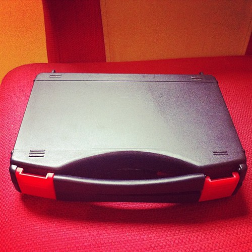
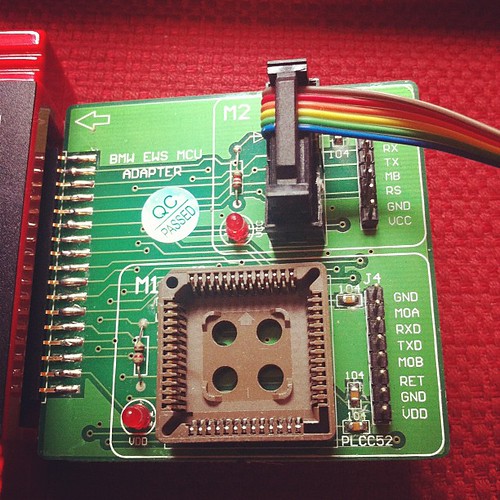
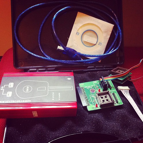
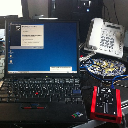
As I’ve had some negative comments about this all being possible, added some photos of the tool I bought to successfully clone my keys.
The box full of goodies.
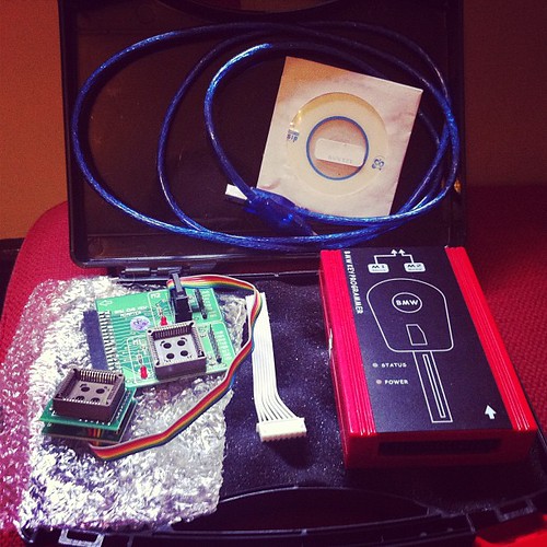
Box contents
Key Cloning tool
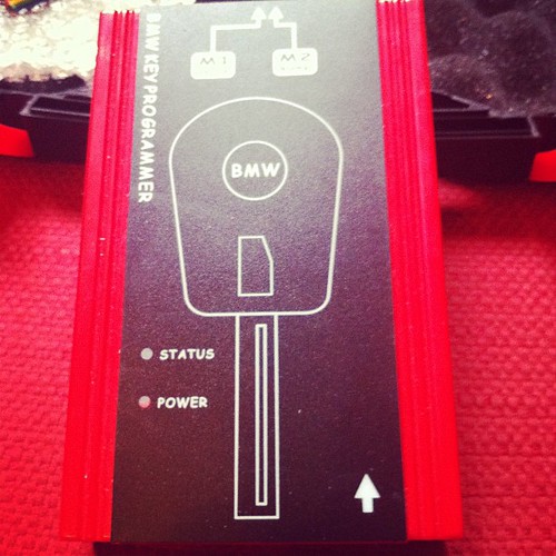
Key Cloning tool side view
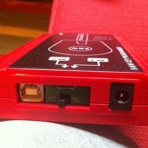
Key Cloning tool MCU adaptor side view
Box contents
Cloned keys (original on far left)
Software Side:
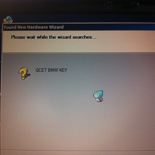
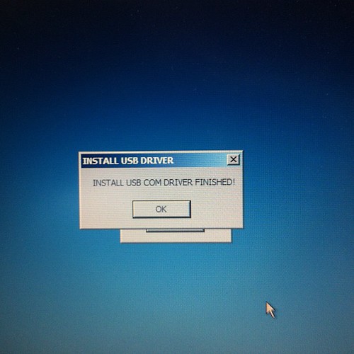
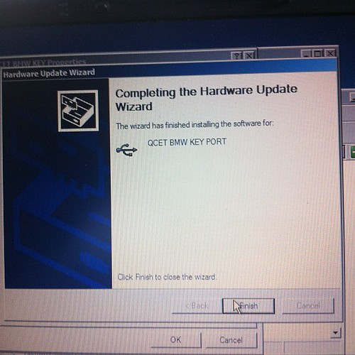
Installing hardware drivers
Device is a standard FTDI usb serial chip based product, needs 2 drivers installed, the first for the serial chip, then a second for the device driven by the usb to serial chip.
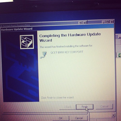
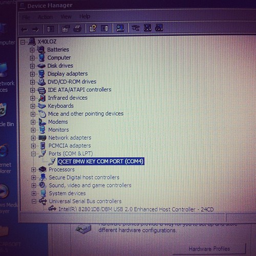
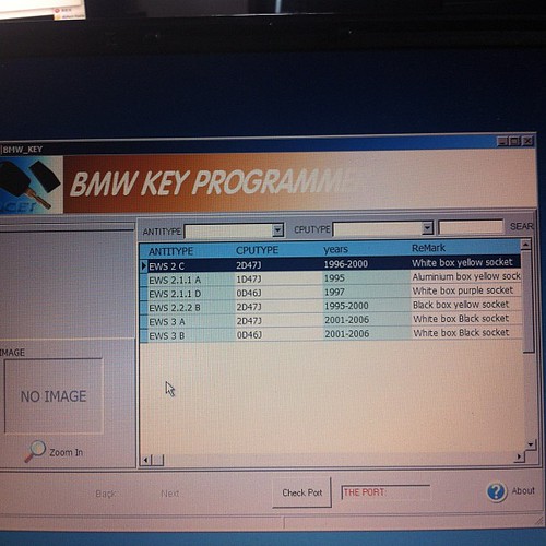
Installing software
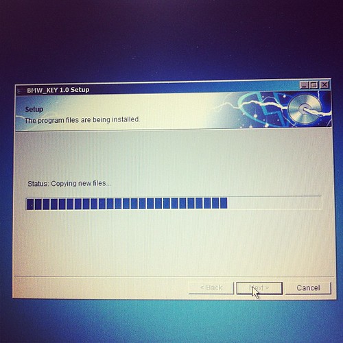
Software running
Archives
- November 2024
- November 2019
- October 2019
- August 2019
- April 2019
- February 2017
- September 2016
- June 2016
- May 2016
- September 2015
- August 2015
- June 2015
- April 2015
- December 2014
- October 2014
- September 2014
- July 2014
- June 2014
- April 2014
- October 2013
- July 2013
- May 2013
- April 2013
- March 2013
- January 2013
- December 2012
- October 2012
- August 2012
- July 2012
- June 2012
- May 2012
- April 2012
- March 2012
- December 2011
- November 2011
- October 2011
- September 2011
- July 2011
- May 2011
- April 2011
- March 2011
- February 2011
- January 2011
- December 2010
- November 2010
- October 2010
- September 2010
- August 2010
- July 2010
- June 2010
- May 2010
- April 2010
- March 2010
- February 2010
- January 2010
- December 2009
- November 2009
- October 2009
- May 2009
- April 2009
- March 2009
- February 2009
- January 2009
- December 2008
- November 2008
- October 2008
- September 2008
Categories
- Apple
- Arcade Machines
- Badges
- BMW
- China Related
- Cool Hunting
- Exploits
- Firmware
- Food
- General Talk
- government
- IP Cam
- iPhone
- Lasers
- legislation
- MODx
- MySQL
- notice
- qmail
- requirements
- Reviews
- Service Issues
- Tao Bao
- Technical Mumbo Jumbo
- Things that will get me censored
- Travel
- Uncategorized
- Useful Info