As visitors to my office have noticed, we’ve been building a bunch of arcade machines for clients.
Here are a couple of pics of the builds in progress:
Chassis’s undergoing painting
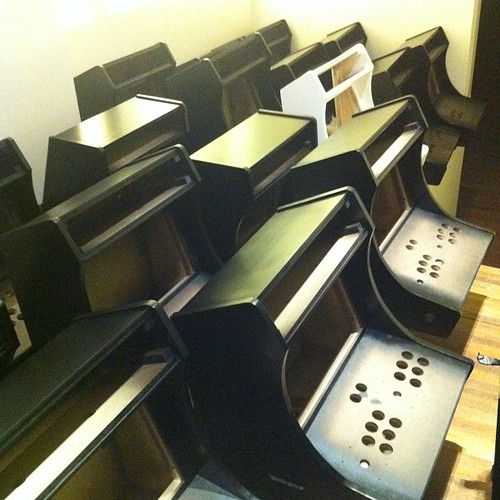
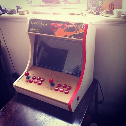
Unfinished machine
While making those is fun, I also have an interest in what powers them.
Arcade Machines are really just a wooden box, a display, a controller board, input (buttons and joysticks), and a PSU, they’re pretty basic devices. There is an industry cabling standard – JAMMA which makes connecting them up nice and easy.
China has a number of hardware choices for powering them, ranging from PC based boards, original arcade boards, and what I think is the better solution for older games – emulation under embedded ARM/MIPS, vs dedicated boards.
We went through a number of different versions of hardware available here until I found something I liked.
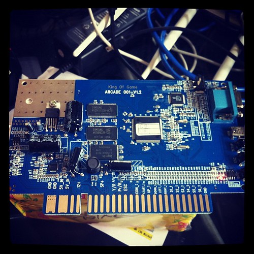
Our currently build hardware du jour runs off of something called “King of Game”.
As is usual in China, no documentation, and the factory is less than forthcoming with information.
Still, not unusual.
The device does have some interesting features for the would be hacker –
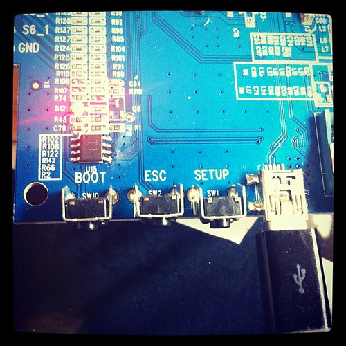
It has a nicely labelled “Boot” button, and the component count is quite low. Which generally means its SoC (System on a Chip) based.
The factory has done a little bit of prep work in making sure us ev1l hackorz won’t get at the juicy bits by etching off the cpu.
A quick look at the chip pin count, and the usual choice of chipset SoC more or less got me the right answer in a few minutes though.
My guess was Ingenic 4850, and it turned out to be the Ingenic 4755. This is a MIPS based X-Burst CPU
Even though they’re Chinese vendor, Ingenic does a great job in providing readily available information about their chipset(s). Kudos to the Ingenic guys in Beijing for being so open!
Datasheets for the 4755 and more importantly toolchains are readily available at the Ingenic FTP site – ftp://ftp.ingenic.cn/2soc/4750
Back to the board.
The King of Game board has USB onboard.
Plugging it into a computer shows the flash files available, but unfortunately not the firmware bits I need to see / change (e.g. to upgrade emulator capabilities, and change graphics).
If I hold down boot and plug in the USB, I get prompted for the Ingenic 4750 drivers.
Those are relatively easy to find on the ingenic site, so get a hold of those yourselves.
In order to connect to the board, you use a USB_BOOT.exe (there are also Linux tools available).
I downloaded usbboot-1.4b usbboot1.4b-tools, and unzipped that.
The USB Boot file needs a config file though – and the default config files supplied didn’t work 🙁
So, off to check what could be up.
The USB_Boot utility requires a bunch of settings in order to communicate with a board. After a bit of fiddling playing around with possible options I got it talking to the board.
While I’m not certain I have the settings completely correct here is what I have right now:
[PLL]
EXTCLK 24 ;Define the external crystal in MHz
CPUSPEED 336 ;Define the PLL output frequency
PHMDIV 3 ;Define the frequency divider ratio of PLL=CCLK:PCLK=HCLK=MCLK
BOUDRATE 57600 ;Define the uart boudrate
USEUART 0 ;Use which uart, 0/1 for jz4740,0/1/2/3 for jz4750
[SDRAM]
BUSWIDTH 16 ;The bus width of the SDRAM in bits (16|32)
BANKS 4 ;The bank number (2|4)
ROWADDR 12 ;Row address width in bits (11-13)
COLADDR 9 ;Column address width in bits (8-12)
ISMOBILE 0 ;Define whether SDRAM is mobile SDRAM, this only valid for Jz4750 ,1:yes 0:no
ISBUSSHARE 1 ;Define whether SDRAM bus share with NAND 1:shared 0:unshared
[NAND]
BUSWIDTH 8 ;The width of the NAND flash chip in bits (8|16|32)
ROWCYCLES 3 ;The row address cycles (2|3)
PAGESIZE 2048 ;The page size of the NAND chip in bytes(512|2048|4096)
PAGEPERBLOCK 64 ;The page number per block
FORCEERASE 0 ;The force to erase flag (0|1)
OOBSIZE 64 ;oob size in byte
ECCPOS 6 ;Specify the ECC offset inside the oob data (0-[oobsize-1])
BADBLACKPOS 0 ;Specify the badblock flag offset inside the oob (0-[oobsize-1])
BADBLACKPAGE 127 ;Specify the page number of badblock flag inside a block(0-[PAGEPERBLOCK-1])
PLANENUM 1 ;The planes number of target nand flash
BCHBIT 4 ;Specify the hardware BCH algorithm for 4750 (4|8)
WPPIN 0 ;Specify the write protect pin number
BLOCKPERCHIP 0 ;Specify the block number per chip,0 means ignore
[END]
If I put the board into USB boot mode (hold down boot button, and plug into the usb), then run the USB_TOOL.EXE file I can communicate
 Welcome!

 USB Boot Host Software!

 USB Boot Software current version: 1.4b

 Handling user command.

 USBBoot :> list
Device number can connect :1
USBBoot :> help
Command support in current version:
help print this help;
boot boot device and make it in stage2;
list show current device number can connect;
fconfig set USB Boot config file;
nquery query NAND flash info;
nread read NAND flash data with checking bad block and ECC;
nreadraw read NAND flash data without checking bad block and ECC;
nreadoob read NAND flash oob without checking bad block and ECC;
nerase erase NAND flash;
nprog program NAND flash with data and ECC;
nmark mark a bad block in NAND flash;
go execute program in SDRAM;
version show current USB Boot software version;
exit quit from telnet session;
readnand read data from nand flash and store to SDRAM;
load load file data to SDRAM;
run run command script in file;
memtest do SDRAM test;
gpios let one GPIO to high level;
gpioc let one GPIO to low level;
sdprog program SD card;
sdread read data from SD card;
USBBoot :> boot
Usage: boot (1)
1:device index number
USBBoot :> boot 0
Checking state of No.0 device: Unboot
Now booting No.0 device:
Download stage one program and execute at 0x80002000: Pass
Download stage two program and execute at 0x80c00000: Pass
Boot success!
Now configure No.0 device:
Now checking whether all configure args valid:
Current device information: CPU is Jz4750
Crystal work at 24MHz, the CCLK up to 336MHz and PMH_CLK up to 112MHz
Total SDRAM size is 16 MB, work in 4 bank and 16 bit mode
Nand page size 2048, ECC offset 6, bad block ID 127, use 1 plane mode
Configure success!
Next up, read the firmware off the flash, and dump it to see which version of the Dingoo code they most probably ripped off 🙂
Do you like this article? Share It!


Archives
- November 2024
- November 2019
- October 2019
- August 2019
- April 2019
- February 2017
- September 2016
- June 2016
- May 2016
- September 2015
- August 2015
- June 2015
- April 2015
- December 2014
- October 2014
- September 2014
- July 2014
- June 2014
- April 2014
- October 2013
- July 2013
- May 2013
- April 2013
- March 2013
- January 2013
- December 2012
- October 2012
- August 2012
- July 2012
- June 2012
- May 2012
- April 2012
- March 2012
- December 2011
- November 2011
- October 2011
- September 2011
- July 2011
- May 2011
- April 2011
- March 2011
- February 2011
- January 2011
- December 2010
- November 2010
- October 2010
- September 2010
- August 2010
- July 2010
- June 2010
- May 2010
- April 2010
- March 2010
- February 2010
- January 2010
- December 2009
- November 2009
- October 2009
- May 2009
- April 2009
- March 2009
- February 2009
- January 2009
- December 2008
- November 2008
- October 2008
- September 2008
Categories
- Apple
- Arcade Machines
- Badges
- BMW
- China Related
- Cool Hunting
- Exploits
- Firmware
- Food
- General Talk
- government
- IP Cam
- iPhone
- Lasers
- legislation
- MODx
- MySQL
- notice
- qmail
- requirements
- Reviews
- Service Issues
- Tao Bao
- Technical Mumbo Jumbo
- Things that will get me censored
- Travel
- Uncategorized
- Useful Info